5AS Module
Overview
Please see the sections below
16 pin OBD/OBDII/OBD2 style cable - 5AS specific
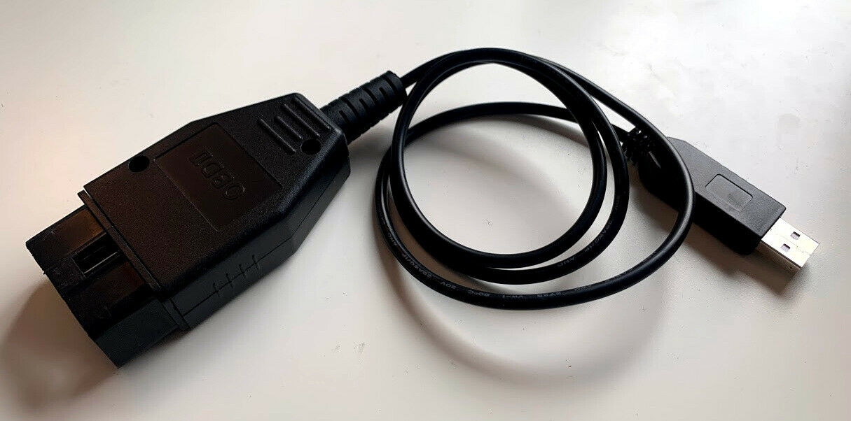
The 5AS modules have a very specific method of communicating, I am testing some custom built 5AS specific cables at the moment and hope to be able to advise on these in the near future
5AS Immobiliser - key fob to immobiliser sync tool
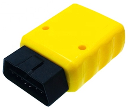
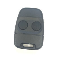
This tool allows you to sync new key fobs to a 5AS immobiliser
(It does not help with linking a 5AS immobiliser to an ECU)
These are to suit all cars with the 5AS immobiliser wired to a 16-pin OBD style diagnostic port.
The MPI Minis have this type of wiring, if you are not sure about another car then send me the correct wiring diagram for your car and I have have a look for you and check.
I am now selling these directly from the website, secure payment taken via stripe.com
I post using Royal Mail with tracking, I will send you the tracking link once the postage has been arranged.
This cheaper version of the tool will sync/lock itself to your immobiliser on first use.
You cannot use it on multiple cars, but you can use it repeatedly on the same car.
This more expensive version of the tool will work on multiple cars and is intended for locksmiths/workshops only, please provide proof of your business when ordering this.
Diagnostic web application for Windows/Mac/Linux
I am working on a diagnostic application for 5AS modules, it is still in progress but works already
In order to use it you will need to use a special cable, I have ordered parts for these and will be able to offer them for sale soon
It will have the ability to check the state of things like door switches, alter settings e.g. passive arming/superlocking, pair key fobs, set immobiliser code for ECU
5AS web application
Technical information - diagnostic communication
In case you are a programmer or would like more info about communication with the ECUs for diagnostics, here it is
It is possible to read and write to the EEPROM over diagnostics - get EKA, change serial number, change settings
It can run at 9600 baud normally but there is code which sets up 1200 baud somehow
5-baud wake ups:
Normal mode - 0x1c - module replies 0x55 0x83 0x76
EEPROM edit mode - 0x9d - module replies 0x55 0x83 0xF7
Commands in Normal mode:
3x commands start tests.
2x commands end tests.
Test items:
x0 (e.g. 0x20 or 0x30) - ?
x1 - ?
x2 - ?
x3 - ?
x4 - ?
x5 - ?
x6 - ?
x7 - ?
x8 - horn
x9 - 5AS led
xa - ?
xb - ?
xc - ?
xd - hazards
xe - ?
xf - ?
Fx commands are the same as the MEMS engine ECUs
0xF6 reset/disconnect from diagnostics
5x commands are for start procedure.
6x commands are for stop procedure.
xF is for fob programming
0x5F - start programming keyfobs
0x6F - end programming keyfobs
0x83 - request data packet
packet response format (not totally clear):
Byte 00 - [size of packet including size byte]
Byte 01 - # bonnet switch 0/0x80 (bit 7)
Byte 02 - ?
Byte 03 - ?
Byte 04 - ?
Byte 05 - ?
Byte 06 - 0x00 # ignition switch 0/0x80 (bit 7)
Byte 07 - ?
Byte 08 - ?
Byte 09 - 0x80 # door switch(es) 0/0x80 (bit 7)
Byte 10 - ?
Byte 11 - 0x80 # swaps 0 to 0x80 for boot(?) switch (bit 7)
Byte 12 - ?
Byte 13 - ?
Byte 14 - ?
Byte 15 - ?
Byte 16 - # counter for key 1
Byte 17 - # counter for key 2
Byte 18 - # counter for key 3
Byte 19 - # counter for key 4
Byte 20 - # Serial number byte 0 - three bytes here, LSByte first
Byte 21 - # Serial number byte 1
Byte 22 - # Serial number byte 2
Byte 23 - ?
Byte 24 - ?
Byte 25 - ?
Byte 26 - ?
Byte 27 - ?
Byte 28 - ?
Byte 29 - ?
Byte 30 - ?
Byte 31 - ?
Byte 32 - ?
Byte 33 - ?
Byte 34 - ?
Byte 35 - 0x41 # A Unit description - data from here onwards is ASCII - reads "AP3.005AS-98MY"
Byte 36 - 0x50 # P
Byte 37 - 0x33 # 3
Byte 38 - 0x2e # .
Byte 39 - 0x30 # 0
Byte 40 - 0x30 # 0
Byte 41 - 0x35 # 5
Byte 42 - 0x41 # A
Byte 43 - 0x53 # S
Byte 44 - 0x2d # -
Byte 45 - 0x39 # 9
Byte 46 - 0x38 # 8
Byte 47 - 0x4d # M
Byte 48 - 0x59 # Y
EEPROM mode:
The commands are basically always interacting with the EEPROM or EPROM/RAM (need to double check which) depending on the address you give
EPROM/RAM is accessed as addresses 0x00-0xFF
EEPROM is accessed as address 0x100-0x1FF
Commands are always 4 bytes long, the fourth byte is always 0xAA
e.g. [0x__, 0x__, 0x__, 0xAA]
If you intend to write then the 3rd byte is the value to be written, if reading then leave it as 0x00
If writing, also set bit 5 of the first byte, clear it otherwise
If accessing an address from 0x100 onwards set bit 6 of the first byte, clear it otherwise
For the address, set the second command byte to address >> 1, and bit 0 of first byte to bit 0 of the address
Read size can be set by setting bits 1,2,3 of byte 0. 1 is added to whatever value you give so input 0-7 to get 1-8 byte replies
Write size is always 1
e.g.
function eeprom(int address, bool write, int value?) {
command = {0x00, 0x00, 0x00, 0xAA};
if (address > 0x1FF) { error out }
command[0] |= address & 1;
command[1] = address >> 1;
if (write) { command[2] = value; }
if (write) { command[0] |= 0b00100000; }
if (address >= 0x100) { command[0] |= 0b01000000; }
Andrew has specific info on the EEPROM data on his website, I have a bit more detail somewhere if I can find it
It seems like there are two copies of everything, the first copy is normal, the second copy of everything is stored in reverse order
For now see: https://andrewrevill.co.uk/5ASCloningPart2.htm
Where Andrew gives an offset (address), he was looking only at the EEPROM so you need to add 0x100 to his addresses
Short version:
Serial number address: 0x19C 0x19D 0x19E
EKA (emergency key access) address: 0x1A0 0x1A1 - stored MSB first, also stored as binary coded decimal e.g. if the two bytes are 0x1234 (hex) then the EKA is 1,2,3,4
Disclaimer: This website is not associated with Rover in any way. This exists because there is no support for these older cars/ECUs
Privacy: Privacy policy
Built 20250417093753