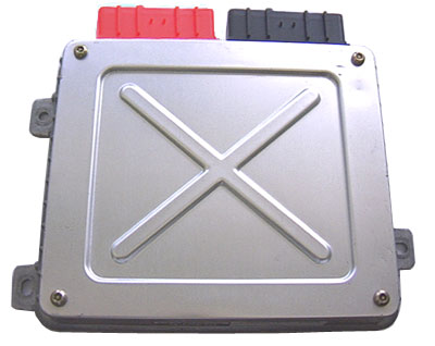
MEMS 2J ECUs
Overview
Please see the sections below for the MEMS 2J ECU
Diagnostic application - Windows/Mac/Linux
The most up to date application is here for Windows/Linux
Web/agent application
This is also a web based application that works in Windows/Max/Linux computers or laptops
Web application
If you need a Windows driver for a 16-pin FTDI based cable then you can download it here:
FTDI driver
Diagnostic application - Android phone and tablet
The Android app works with MEMS 2J ECUs while using an appropriate cable.
The cables are full size USB so you will likely need to buy an "OTG" adaptor that fits between your device and the USB cable.
Android app in the Google Play store
Remapping
It is possible to modify 2J ECUs to allow them to be remapped.
Either a simple version where the chip must be removed for each set of mapping changes, then reintalled,
or a more advanced version where the ECU can be mapped with the engine running e.g. on a rolling road or road tuning.
It is possible to modift these by desoldering the main memory chip and installing a chip socket.
Then utilising a new rewritable chip and external programmer it is possible to edit the maps.
I would suggest this should only be done by someone very skilled in soldering work and PCB repair, it is very easy to lift a pad and ruin an ECU doing this
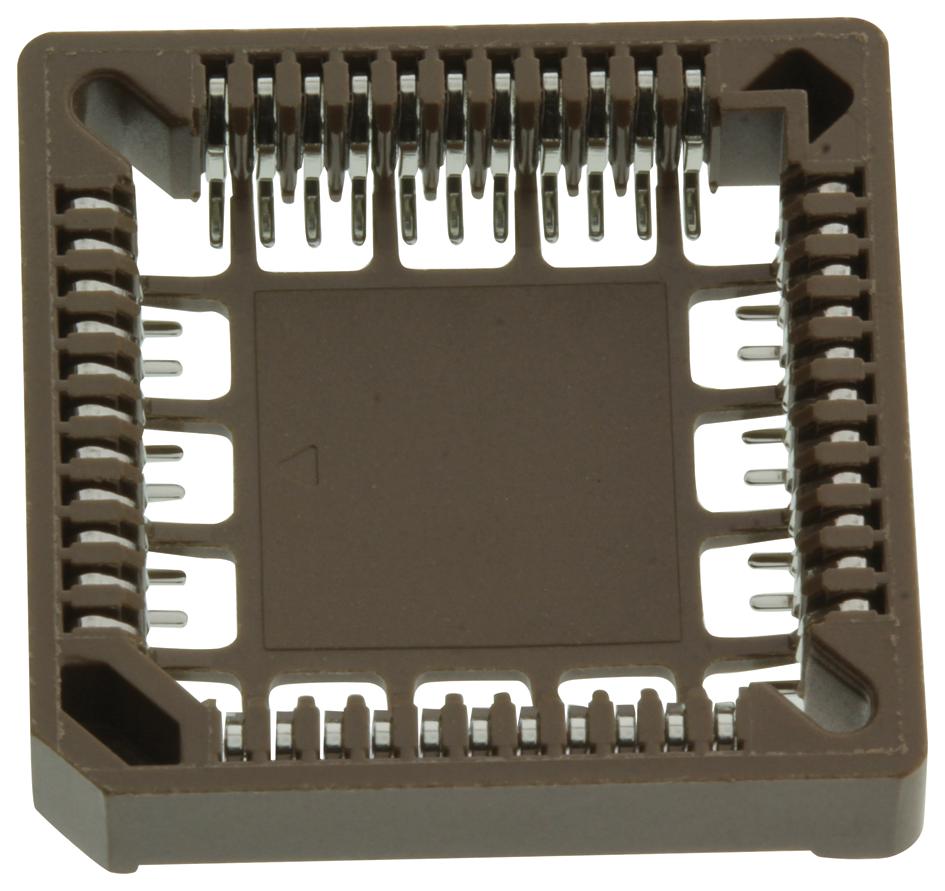
Parts needed:
- PLCC-44 surface mount socket
- AT49F1025 chip - ideally industrial rated, the different response time variations should all be fast enough, if in doubt get 70ns version
- EEPROM programmer - suggest the TL866II Plus which supports the above chip
- Otherwise AT29C1024 and the T56 programmer
- Adaptor for chip into the programmer, some do come with the right adaptor board already (it is not a straightforward PLCC-44 to DIP adaptor, some of the pins are different)
- New ECU lid if you damage the existing one while removing - I have some laser cut aluminium lids
PLCC-44 Socket
The modification includes: an expansion board fitted inside the ECU, a new rewritable chip, a brand new laser cut aluminium ECU lid. A diagnostic cable is supplied which is used for mapping changes as well as general diagnostics.
Map updates can be done "live" with the engine running, the active table cell is highlighted to help with steady state/rolling road tuning.
This took a lot of work in designing and testing the expansion board as well as making ECU code patches to allow the map changes to be saved permanently.
Here is a short video of the live remapping on the 2J ECUs
It shows the initial data download from the ECU and then shows looking through a few tables.
You can see the active cell highlighting which allows you to see which table cell the ECU is currently using while the engine runs
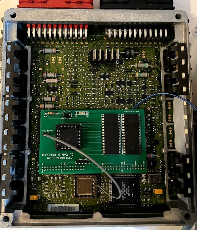
Modified 2J ECU with additional board to allow OBD remapping
MAP sensor scaling calculator
Use this to work out MAP sensor scaling values needed when fitting a different MAP sensor to an ECU.
This could be used to allow the stock ECU to work on a boosted (turbo/supercharged) engine.
The ECU circuitry on the input pin causes a voltage drop, this is accounted for by the multiplier setting.
The voltage drop multiplier is set for MPI Mini (2J) ECUs by default.
MEMS 2J Mini MPI: 0.896
MEMS 3: 0.833
TD5: 0.907
ECU sensor voltage drop multiplier:
Known kPa values vs voltage:
kPa at 0v:
kPa at 5v:
Values for ECU maps:
Multiply:
Divide:
Add (offset):
Known ECU map values:
Multiply:
Divide:
Add (offset):
kPa at voltage:
kPa at 0v:
kPa at 5v:
Technical information - diagnostic communication
In case you are a programmer or would like more info about communication with the ECUs for diagnostics, here it is
5-baud wake up or fast-init (25ms break followed by 25ms non-break)
Only some cables allow breaks to be used properly - FTDI chips always work
Then use 10400 Baud rate, 8 bits, 1 stop bit, NO parity
K-line communication over a single wire
You literally get your own transmissions as echos because it is K-line
Uses KWP-2000
Normal packets structure is - [format] [dest] [source] [length of data bytes] [data bytes ...] [checksum]
The checksum is a SUM of all data bytes and the length byte, then cropped to 1 byte in case it has spilled over 255 (AND it with 0xFF)
After doing fast or slow init, send bytes to the ECU: 0x81, 0x13, 0xF7, 0x81, 0x0C - this is a one-off packet just to init/get in, no length byte sent
ECU should reply 0x03, 0xC1, 0xD5, 0x8F, 0x28 - again this is a one-off packet
After that it is just KWP2000
Disclaimer: This website is not associated with Rover in any way. This exists because there is no support for these older cars/ECUs
Privacy: Privacy policy
Built 20250417093753