Discussion posts
Mini MPI Injection Timing - Siamese intake ports
There is a lot of talk about the huge effect that the siamese intake ports have on the MPI Mini engine, and the way that it must be run, but very little in the way of evidence.The main issue is that the outer cylinders rob charge from the inners, but how bad is it? And how well have the Rover engineers worked around this by using variable injection timing on the MPI engine?
It would be great if someone could just hook up a lambda sensor and EGT probe into each exhaust manifold outlet and report back.
I have heard that some people have claimed to do this, but I have not seen any evidence or results
I have spent a lot of time working through the MPI Mini's ECU code and have some information to share around how the injection timing is done.
This may already be known to some, but I have found it very difficult to get hold of any specific information so far, so hope this helps to some degree.
First of all, it does not seem that injection timing is changed between inner/outer cylinders, it seems as though the injection timing is just shifted earlier or later for all cylinders at the same time
I believe the maps are done as degrees crank angle in a 720 degree full cycle - two revs
Elsewhere in the ECU there are offsets for each injection in degrees per 720 degree cycle - 0 (same as 720)(cyl 1), 540 (cyl 2), 180 (cyl 3), 360 (cyl 4)
This matches the expected firing order if you take the injections in the order they happen in degrees - 1-3-4-2
The offsets mean that the maps can be created as if you were writing them for cylinder 1, then the offsets are applied depending which cylinder is currently in use
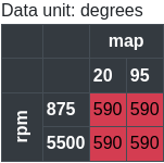
Map 62 - base injection timing below 10 RPM
The first map in the ECU regarding the injection timing is map 62 - base injection timing when below 10 RPM
It is not entirely clear if this table will ever be used, since even during cranking, the RPM will be several hundred RPM
In any case, the values set are close to the values in the next table around idle and cranking areas, so it will not make a huge difference
You could for instance edit the 10 RPM value in the ECU and raise that value to 600 RPM, in which case this would become a map that kicks in during cranking, it could be that the engineers were testing ways to make the engine start more easily but may not have used or needed it in the end
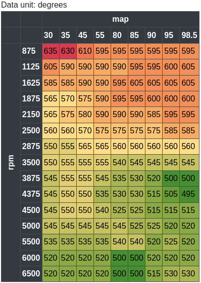
Map 63 - base injection timing above 10 RPM
The second map is the main one for injection timing when above 10 RPM - map 63
This is the "base" injection timing for normal engine running, it works based on manifold pressure vs RPM
Variables affect fuelling
As is the case with normal engine management, fuelling is affected by temperature, pressure, and gas speed (RPM), this can also be taken into account when setting the injection timing
The base map above already takes into account manifold pressure vs RPM, but that map assumes the car is up to normal operating temperature of 80+ degrees coolant temperature
The next two maps additionally alter the injection timing during warm-up (below 80 degrees coolant temp) as well as above normal operating temperatures (100+ degrees coolant temp)
The lowest value of the two read from map 64 and 65 is used and added to the "base" value from map 63
These maps are probably influenced somewhat by some of the other maps in the ECU which alter ignition timing during warm-up and overheat situations
Drastically changing the ignition timing could well alter the required injection timing...
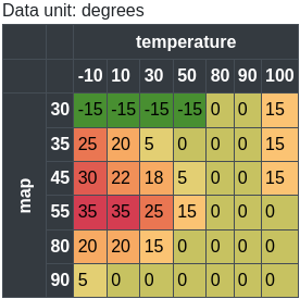
Map 64 - injection timing offset - coolant temperature vs manifold pressure
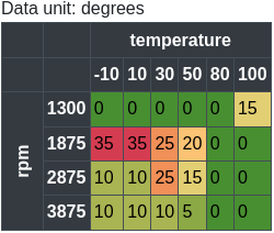
Map 65 - injection timing offset - coolant temperature vs RPM
Contact: email me
Disclaimer: This website is not associated with Rover in any way. This exists because there is no support for these older cars/ECUs
Privacy: Privacy policy
Disclaimer: This website is not associated with Rover in any way. This exists because there is no support for these older cars/ECUs
Privacy: Privacy policy
Built 20250417093753