Discussion posts
Koso dashboard bouncing RPM signal
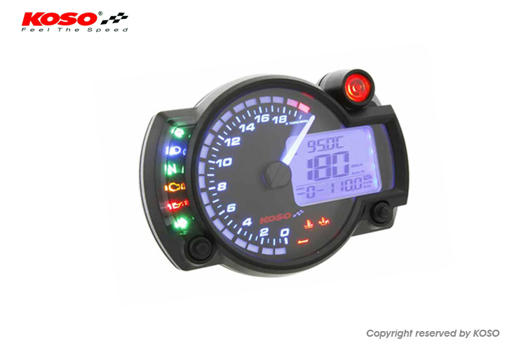
I recently fitted a Koso RX-2N+ dash to a car with an aftermarket ECU
They build a version with a 10,000 RPM limit which is suitable for road cars, as opposed to the 20,000 RPM version which is definitely just for bikes
It comes with a number of configurable inputs including fuel level, wheel speed, oil and coolant temperature sensors
Upon wiring the RPM/tach signal to the car's coil pack I saw very noisy and unstable RPM signal
Googling this revealed a large number of other people with the same issue on their cars and bikes
There are various suggested fixes from basic resistors to more complicated filter circuits
As it happens, the aftermarket ECU was CAN bus equipped and already broadcasts engine data out many times per second
I decided to use the CAN data via an Arduino, and relay that to the dash as a perfectly clean signal from an Arduino output pin
In future I can do the same with the coolant temperature data from the ECU, rather than adding another temperature sensor just for the dash, I could use the CAN data to drive the dash coolant temperature (it may need to go through a digital potentiometer or similar)
The CAN data parsing is unique to this ECU so I will not post it here
The working for the RPM output signal from Arduino to Koso dash is as follows:
Using an Arduino with a 5v GPIO signal level, you can simulate a spark event by setting the output high (5v) for a small amount of time, then setting it back to low (0v)
If you know the RPM speed then it is a case of working out how long you need to wait between simulating spark events
The dash also has a multiplier so that you can provide different types of inputs and end up with the correct RPM displayed e.g. feeding it one spark plug signal on a 4 cylinder engine, you would need to double it for RPM as you would be getting the number of engine cycles otherwise
To simplify the code I decided to emulate one spark event per engine rotation and output an evenly spaced square wave - the high and low of each spark event will be the same length of time, together they will add up to the amount of time between spark events at the current RPM
The time in microseconds between spark events for a certain RPM can be calculated with: pulseIntervalUs = 60,000,000 / RPM
The longer explanation for this is that the timescales for spark events go down to microsecond values
7,000 RPM is equal to 116.66 (recurring) revolutions per second (7000/60)
This means that the time per revolution for 7,000 RPM is around 0.00857 seconds (1/116.66)
The time per revolution at 6,900 RPM is around 0.00869 seconds
This gives an idea that even milliseconds would not be accurate enough as this would be 8.57ms vs 8.69ms, so 9ms would have to be used with the Arduino delay function, leading to the dash display being incorrect by hundreds of RPMs
The 60,000,000 value is derived from the number of microseconds in a minute
1 minute = 60 seconds = 60,000 milliseconds = 60,000,000 microseconds
Dividing this value by RPM gives microseconds per rev
In my code I set the high signal to the dash for half of that calculated time value, and set the low signal for half of the calculated time again
I also constantly monitoring the CAN data and update the time interval as RPM changes
In doing so I now have an extremely stable RPM display on the Koso dash
Contact: email me
Disclaimer: This website is not associated with Rover in any way. This exists because there is no support for these older cars/ECUs
Privacy: Privacy policy
Disclaimer: This website is not associated with Rover in any way. This exists because there is no support for these older cars/ECUs
Privacy: Privacy policy
Built 20250417093753